Ceramic Blade Ordering Information
Ceramic Blade Order Information

Standard Tip Length is .007”.
Other Tip Lengths require Depth changes.
New Ceramic Blade Types are continually being added. All styles of Ceramic Blades may be available from ICT. If you need a style not shown please call your ICT representative and we would be happy to satisfy your needs in a timely manner.
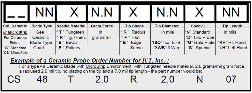
Part Number Guide

Glossary of Terms
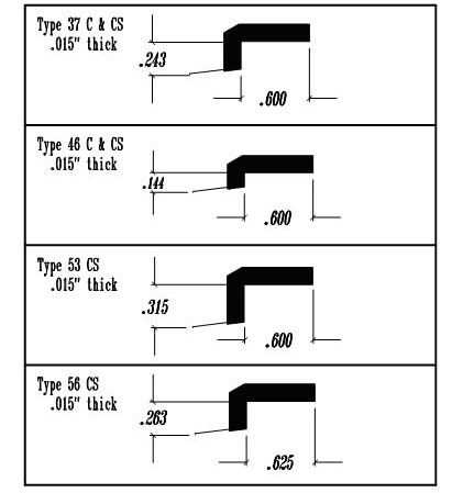
Ceramic Blade Type
- Choose the style of blade that is needed for the probing operation’s specific needs. Choose the type with the correct “ Tip Depth” for your application (see chart). Blades are available in Metal and Ceramic materials. For Ceramic types, please precede the Part Number with “C” for standard Ceramics and “CS” for MicroStrip Ceramics. See application note #55 on Ceramic Blades for more details. Another important variable to take into consideration is the actual height of the blade from the board which may cause interference with the test head. See ICT’s “Blade Type” chart for specific types.
Needle Material
- Tungsten (T) is most common material chosen by users. It has a very low wear rate , so its life is long. Initial contact resistance readings are low, but it needs to be cleaned often to maintain these values.
- Tungsten Rhenium (R) requires less frequent cleaning than tungsten. Therefore it has a more consistent contact resistance over its life than pure tungsten. Some users witness longer life.
- Beryllium Copper (B) used primarily for probing gold pads. It has low contact resistance throughout its life. This material wears faster and hence has a shorter life span than tungsten based materials.
- Paliney (P) gives the best results on contact resistance readings. It exhibits the highest wear rate, thus the shortest life span.
- See ICT’s Application Note # 21 “ Contact Resistance - Effects of Materials and Dimensions”
Gram Force
- This is the measure of force the tip exerts per 1 mil of overdrive. This force is necessary force to break through any oxides and allows the tip to scrub the die’s pad material for good electrical contact. Generally, 2.0 grams of force per mil of overdrive is recommended. (1.5 to 3 grms/mil is standard)
- See ICT’s Application Note # 21 “Contact Resistance - Effects of Materials and Dimensions”
Tip Shape
- Flat (F) tips, when overdriven, “heel” up to break the oxides on the pad and plow them up in order to make an electrical contact.
- Radius (R) tips tend to pierce the oxides on contact and push them out of the way to make a more aggressive electrical contact.
Tip Diameter
- This characteristic can be determined by considering the pad size of the die being probed. The general rule is, the tip diameter to be used should be no more than 50% of the total pad size of the device to be probed. For example: to probe a 4 mil by 4 mil pad, use no more than a 2 mil needle tip. ICT’s standard tip diameters are .5 to 2 mils, as well as 5 mil and 10 mil standards.
Plating
- None (N): Tip of the needle has no plating.
- Gold (G): Tip of needle is plated gold. Usually associated with edge sensor probes.
- Special (S): Used to designate any extraordinary characteristic. Note this characteristic on your PO.
Tip Length
- Standard tip length for wafer probing is 7 mils. Hybrid probing requires a longer tip so that the needle does not hit components that may be mounted on the substrate. The standard tip length for Hybrids is 20 mils.
Tip Angle
- Although not part of the official part numbering system, tip angle can be important. ICT recommends a steep angle of 11 to 15 degrees to reduce the motion of the probe tip with wear. Angles of 18 to 22 degrees are typically seen in the industry. ICT can produce any tip angle. Let ICT know your desire.


